作者:富贵人
1.串行通信的基本概念
串行是与并行想对应的,并行通信是指数据的各位同时被传送。串行通信是将要传送的数据一位位的依次顺序发送。
串行通信实现的是两个对象之间的数据传递,对象通常是单片机。通信实际上是在两个单片机上连上线,通过线路来传递信息。
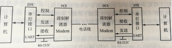
如图,调制解调器非常重要,其作用是实现数字信号和模拟信号的转换。但是注意,调制解调器是远距离传输才有用。近距离传输不需要调制解调器(零Modem方式)。因此进行单片机的实验只需要将相应接口的线路连好就行。连接示意图如图

2.STM32单片机与电脑串行通信
1.信号线的连接
单片机与电脑通信通常用的是USB接口连接电脑。那么就需要首先将串口转为USB,STM32上有相应的硬件实现该功能,我们只需要看电路图线路是否连接。
以下是正点原子miniSTM32的连线步骤:
(1)查单片机电路图,找到主板芯片上的U1_RXD与U_TXD接口。
(2)找到USB_232的RXD与TXD接口
(3)如果电路图上线路未连接,将主板芯片的U1_RXD通过跳线与USB_232上的TXD连接,主板芯片的U1_TXD通过跳线与USB_232上的UXD连接。
2.程序的编写
由于采用STM32官方固件库,因此编写串口通信程序非常简单。
思路:
(1)初始化串口
(2) 调用USART_SendData函数向串口发送数据。
其中初始化串口包括
1) 串口时钟使能,GPIO 时钟使能
2) 串口复位
3) GPIO 端口模式设置 端口模式设置
4) 串口参数初始化
5) 开启中断并且初始化 NVIC (如果需要开启中断才这个步骤 )
6) 使能串口
7) 编写中断函数
那么最简单的串口通信程序如下,注意,由于没有编写中断函数,此程序只发不收。发送的数据永远是01。
代码1
#include "stm32f10x.h"
void my_delay_ms(int time);
void my_delay_ms(int time)
{ int i=0;
while(time--)
{
i=12000;
while(i)
{
i--;
}
}
}
void uart_init(u32 bound){ //GPIO端口设置
GPIO_InitTypeDef GPIO_InitStructure;
USART_InitTypeDef USART_InitStructure;
NVIC_InitTypeDef NVIC_InitStructure;
RCC_APB2PeriphClockCmd(RCC_APB2Periph_USART1|RCC_APB2Periph_GPIOA, ENABLE); //使能USART1,GPIOA时钟
//USART1_TX GPIOA.9
GPIO_InitStructure.GPIO_Pin = GPIO_Pin_9; //PA.9
GPIO_InitStructure.GPIO_Speed = GPIO_Speed_50MHz;
GPIO_InitStructure.GPIO_Mode = GPIO_Mode_AF_PP; //复用推挽输出
GPIO_Init(GPIOA, &GPIO_InitStructure);//初始化GPIOA.9
//USART1_RX GPIOA.10初始化
GPIO_InitStructure.GPIO_Pin = GPIO_Pin_10;//PA10
GPIO_InitStructure.GPIO_Mode = GPIO_Mode_IN_FLOATING;//浮空输入
GPIO_Init(GPIOA, &GPIO_InitStructure);//初始化GPIOA.10
//Usart1 NVIC 配置
NVIC_InitStructure.NVIC_IRQChannel = USART1_IRQn;
NVIC_InitStructure.NVIC_IRQChannelPreemptionPriority=3 ;//抢占优先级3
NVIC_InitStructure.NVIC_IRQChannelSubPriority = 3; //子优先级3
NVIC_InitStructure.NVIC_IRQChannelCmd = ENABLE; //IRQ通道使能
NVIC_Init(&NVIC_InitStructure); //根据指定的参数初始化VIC寄存器
//USART 初始化设置
USART_InitStructure.USART_BaudRate = bound;//串口波特率
USART_InitStructure.USART_WordLength = USART_WordLength_8b;
USART_InitStructure.USART_StopBits = USART_StopBits_1;//一个停止位
USART_InitStructure.USART_Parity = USART_Parity_No;//无奇偶校验位
USART_InitStructure.USART_HardwareFlowControl = USART_HardwareFlowControl_None;
USART_InitStructure.USART_Mode = USART_Mode_Rx | USART_Mode_Tx;
USART_Init(USART1, &USART_InitStructure); //初始化串口1
USART_ITConfig(USART1, USART_IT_RXNE, ENABLE);//开启串口接受中断
USART_Cmd(USART1, ENABLE);//使能串口1
}
uint16_t str=1;int main()
{
u16 times=0;
uart_init(115200);
while(1)
{
times++;
my_delay_ms(10);
if(times%10000)
{
USART_SendData(USART1, str);//向串口1发送数据
while(USART_GetFlagStatus(USART1,USART_FLAG_TC)!=SET);
}
}
return 0;
}
在PC端打开串口调试助手,可以看到不断接收到数据01

3.linux系统单片机与电脑串行通信
1.信号线的连接
本系统采用讯为的开发板,开发板装的为linux系统,由于开发板自带UART(串口)接口,因此使用UART转USB线,一端连开发板的UART接口,一端连电脑的USB就行了,打开串口调试助手,就可以查看串口数据了。
2.程序的编写
思路:
(1)在linux系统下安装串口驱动
(2)编写串口发送函数
串口发送函数步骤为:
1)fopen打开串口对应的设备
2)设置参数,如波特率等
3)使用write函数向串口中写数据
代码和第4节类似。
打开串口调试助手,就能在电脑屏幕上看到所发送的数据了。
4.STM32单片机与linux系统单片机串行通信
1.信号线的连接
如果单片机都能和电脑通信,那么两个单片机的串口通信,只需要将串口线连接起来就行,准备三根跳线,第一根连接单1的RXD和单2的TXD,第二根连接单1的TXD和单2的RXD,第三根连接单1的GND和单2的GND。OK,可以发送数据了。
2.程序的编写
本代码实现下位机STM32发送数字1,上位机linux系统单片机接受到数字1并打印出来。
1.STM32程序和代码1一样,简单的不断发送1。
2.linux系统单片机代码如代码2,简单不断读发送的数据并输出。
代码2
#include <stdio.h>
#include <string.h>
#include <unistd.h>
#include <sys/types.h>
#include <sys/stat.h>
#include <fcntl.h>
#include <termios.h>
#include <errno.h>
int set_opt(int,int,int,char,int);
void leds_control(int);
int main(int argc, char* argv[])
{
printf("hello,run ok\n");
int fd, read_num = 0;
char buffer[1024],buffer_test[1024];
memset(buffer, 0, 1024);
memset(buffer_test, 0, 1024);
if(argc < 2)
{printf("usage: ./uarttest /dev/ttySAC3\n");return 0;
}if((fd = open(argv[1], O_RDWR|O_NOCTTY|O_NDELAY))<0)
{printf("open %s is failed\n", argv[1]);
return 0;
}
else{
set_opt(fd, 115200, 8, 'N', 1);
int n=10000000;
int k=0;
while(k<n){
k++; printf("%d\n",k);
sleep(1);
memset(buffer, 0, 256);
read_num = read(fd, buffer, 255);
printf("read_num=%d\n",read_num);
if(read_num>0){printf("%s\n",buffer);
}else{printf("read error\n");
}
}
fd=close(fd);
}return 0;
}
int set_opt(int fd,int nSpeed, int nBits, char nEvent, int nStop)
{ struct termios newtio,oldtio;
if( tcgetattr( fd,&oldtio) != 0) {
perror("SetupSerial 1"); return -1;
}
bzero( &newtio, sizeof( newtio ) );
newtio.c_cflag |= CLOCAL | CREAD;
newtio.c_cflag &= ~CSIZE; switch( nBits )
{ case 7:
newtio.c_cflag |= CS7; break; case 8:
newtio.c_cflag |= CS8; break;
}switch( nEvent )
{case 'O':
newtio.c_cflag |= PARENB;
newtio.c_cflag |= PARODD;
newtio.c_iflag |= (INPCK | ISTRIP);break;case 'E':
newtio.c_iflag |= (INPCK | ISTRIP);
newtio.c_cflag |= PARENB;
newtio.c_cflag &= ~PARODD;break;case 'N':
newtio.c_cflag &= ~PARENB;break;
}
switch( nSpeed )
{case 2400:
cfsetispeed(&newtio, B2400);
cfsetospeed(&newtio, B2400);break;case 4800:
cfsetispeed(&newtio, B4800);
cfsetospeed(&newtio, B4800);break;case 9600:
cfsetispeed(&newtio, B9600);
cfsetospeed(&newtio, B9600);break;case 115200:
cfsetispeed(&newtio, B115200);
cfsetospeed(&newtio, B115200);break;case 460800:
cfsetispeed(&newtio, B460800);
cfsetospeed(&newtio, B460800);break;case 921600:
printf("B921600\n");
cfsetispeed(&newtio, B921600);
cfsetospeed(&newtio, B921600); break; default:
cfsetispeed(&newtio, B9600);
cfsetospeed(&newtio, B9600); break;
}if( nStop == 1 )
newtio.c_cflag &= ~CSTOPB; else if ( nStop == 2 )
newtio.c_cflag |= CSTOPB;
newtio.c_cc[VTIME] = 0;
newtio.c_cc[VMIN] = 0;
tcflush(fd,TCIFLUSH); if((tcsetattr(fd,TCSANOW,&newtio))!=0)
{
perror("com set error");return -1;
}
return 0;
}
本文转载自: 开源嵌入式
声明:本文为转载文章,转载此文目的在于传递更多信息,版权归原作者所有,如涉及侵权,请联系小编邮箱:cathy@eetrend.com 进行处理。